
Online Catalog
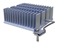
QSZ CLIP
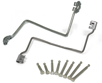
Clips and Anchor pins
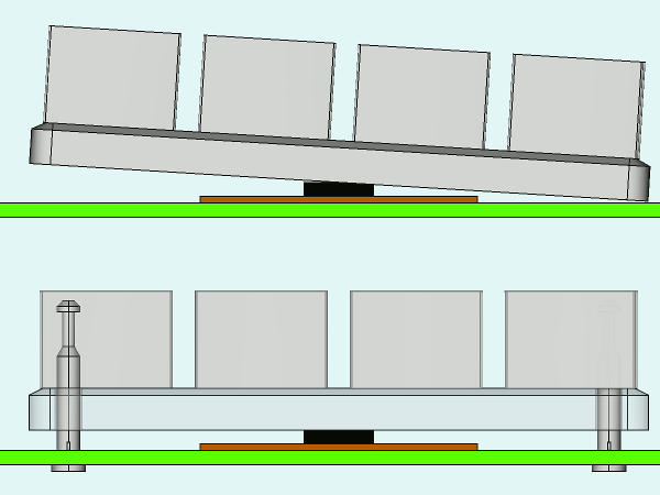
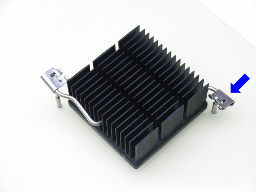
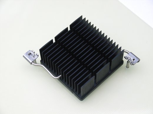
Installation Image
CQZ & QSZ clips are an original mechanical attachment option developed by Alpha.Anchor pins are mounted in the PCB, and the CQZ & QSZ clips secure the heat sink to the anchor pins while generating the attachment force and pressure. PCB thickness, device height, and anchor spacing will vary for each application. Review the following in order to select the most appropriate CQZ & QSZ clip, anchor pin, and heat sink combination.
INDEX
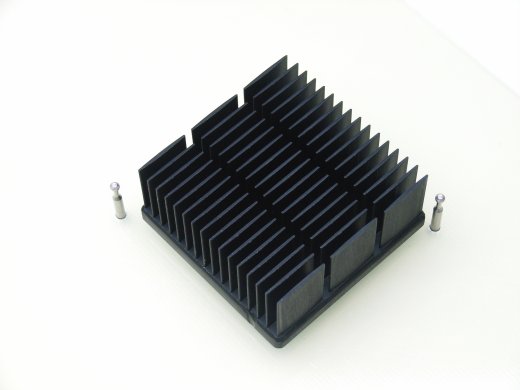
Alpha offers CQZ and QSZ clips, depending on PCB hole diameter and load capacity.
|
CQZ clip & CNCR anchor pin
|
QSZ clip & ANCR anchor pin
|
|
|---|---|---|
 |
||
| PCB hole diameter (mm) | Φ 1.5 +/-0.05 |
Φ 1.8 +/-0.05 |
| Suggested Heatsink Size | Max 50x50mm |
Max 60x60mm |
| Clip Name Prefix | CQZ | QSZ |
| Anchor Name Prefix | CNCR | ANCR |
| CQZ Model | Anchor Pin Layout X x Y (mm) |
Downloads | Availability / Price / Order | ||
|---|---|---|---|---|---|
| Data Sheet | Others | ||||
| 25 x 25 |
|
|
|||
| 30 x 30 | |||||
| 30 x 35 | |||||
| 35 x 40 | |||||
| 40 x 45 | |||||
| 40 x 50 | |||||
| 40 x 55 | |||||
|
PCB Hole Φ1.5 +/-0.05 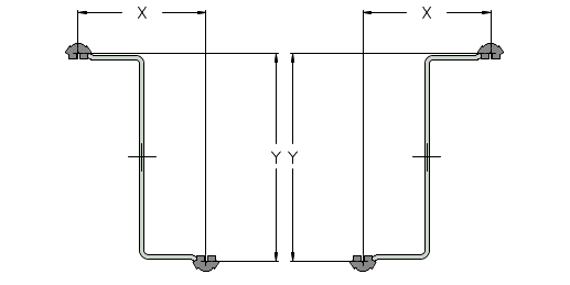
|
25 x 25 | ||||
| 30 x 30 | |||||
| 30 x 35 | |||||
| 35 x 40 | |||||
| 40 x 45 | |||||
| 40 x 50 | |||||
| 40 x 55 | |||||
| QSZ Model | Anchor Pin Layout X x Y (mm) |
Downloads | Availability / Price / Order | ||
|---|---|---|---|---|---|
| Data Sheet | Others | ||||
|
PCB Hole Φ1.8 +/-0.05 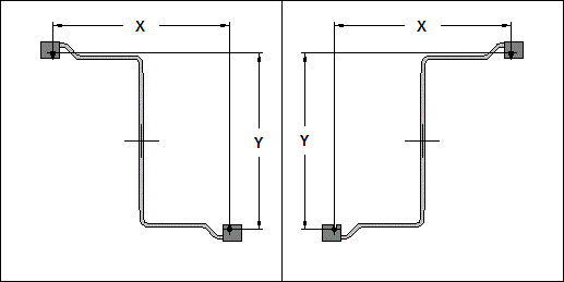
|
24 x 24 |
|
|
||
| 29 x 29 | |||||
| 34 x 34 | |||||
| 39 x 39 | |||||
| 44 x 44 | |||||
| 49 x 49 | |||||
| 54 x 54 | |||||
| 58 x58 | |||||
| 64 x 64 | |||||
|
PCB Hole Φ1.8 +/-0.05
|
24 x 24 | ||||
| 29 x 29 | |||||
| 34 x 34 | |||||
| 39 x 39 | |||||
| 44 x 44 | |||||
| 49 x 49 | |||||
| 54 x 54 | |||||
| 58 x 58 | |||||
| 64 x 64 | |||||
| Create Custom Size | |||||
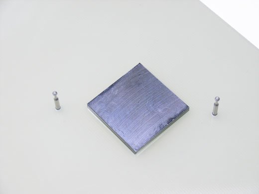
Anchor pins remain captive to the PCB, with no solder required.
| CNCR Model | Size Z (mm) |
Downloads | Availability / Price / Order | ||
|---|---|---|---|---|---|
| Data Sheet | Others | ||||
|
PCB Hole Φ1.5 +/-0.05 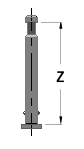
|
8 |
|


|
|
|
| 9 | |||||
| 10 | |||||
| 11 | |||||
| 12 | |||||
| 13 | |||||
| 14 | |||||
| 15 | |||||
| 16 | |||||
| ANCR Model | Size Z (mm) |
Downloads | Availability / Price / Order | ||
|---|---|---|---|---|---|
| Data Sheet | Others | ||||
|
PCB Hole Φ1.8 +/-0.05 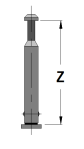
|
8 |
|
|
|
|
| 9 | |||||
| 10 | |||||
| 11 | |||||
| 12 | |||||
| 13 | |||||
| 14 | |||||
| 15 | |||||
| 16 | |||||
Small PCB Area
Easy-Install

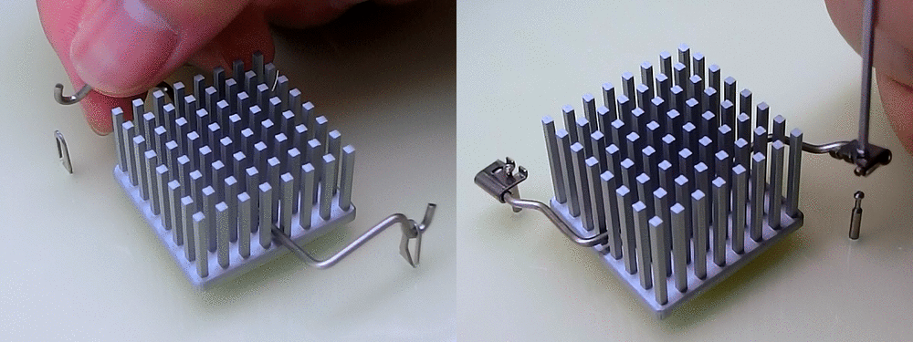
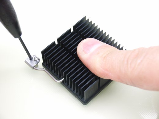
During heat sink installation, traditional Z-Clips may require the heat sink to be slightly twisted or tilted in order for the clip to engage with the board mounted anchor. This could possibly damage any pre-applied thermal interface material or even the device package or exposed die. The CQZ & QSZ clip can be installed without requiring any twisting or tilting of the heat sink.
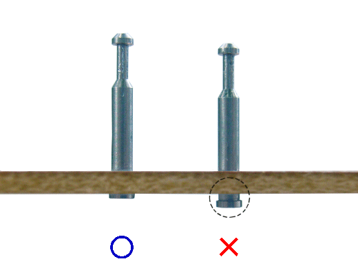
Location and Orientation Guide
Minimize bare-die damage during heat sink installation
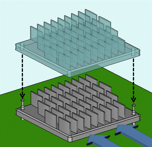
If a heat sink is accidentally installed in the wrong orientation relative to the airflow direction, this could result in serious thermal issues. The heat sink layout can be designed to incorporate anchor pin locations inside the heat sink footprint. The anchor pins would have to pass through holes in the heat sink, ensuring proper orientation.
Exposed dies can be damaged if the heat sink attachment load is applied to the edges or corners of the die. This can happen if the heat is tilted during installation. If the anchor pins are located inside of the heat sink footprint, they will act as guides when the heat sink is installed. The tight clearance between the anchor pins and the clearance holes will greatly reduce the ability of the heat sink to tip or tilt during installation, preventing contact with the edges or corners of the die.
Guidance for installing procedure
1. Align the heat sink with the chip and anchor pins.
1-1. Confirm that the anchor pin is fully inserted.
2. Gently place the heatsink on the top of the chip.
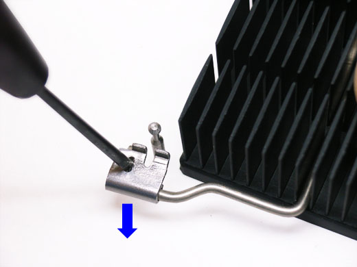
3. Attach one end of the clip’s hook plate to the
anchor pin. Attach the hook plate by bringing it in
from the outside and locking it into the pin.
(follow arrow direction)
4. While applying light pressure to the heat sink to keep it level, lock in the hook plate on the opposite side.
4-1. Detail of locking procedure:Push the hook plate down.
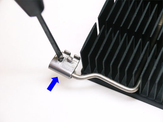
4-2. Slide the hook plate in, toward the anchor pin. Make sure the hook plate slides in under the anchor pin head. Release the hook plate, locking it in place. Inspect the hook plate and pin head to ensure the hook plate is firmly seated and locked.
5. Done!
V (vertical) type
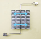
AIR FLOW
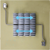
H (horizontal) type
AIR FLOW
Regarding pairing with standard heat sinks, please refer to the following paring table.
- This table only lists the physical dimensions as OK or not OK. Please consult Selecting a heat sink to determine if the heat sink will meet the thermal requirements.
- In some cases, the clip may not be able to contact the exact center of a particular heat sink. This will depend on the fin pattern, air direction, and other factors.
- Please check for fit and ease of attachment when using one of these wire clips. In some cases, installation can be difficult, requiring a twisting motion to install the clip and heat sink.
- This table displays heat sink and CQZ & QSZ clip pairings based on the direction of clip attachment. With the V type (right above photo), the CQZ & QSZ clip run perpendicular (opposite) of airflow/fin direction. The H type (right bottom photo) runs parallel (inline) with the airflow/fin direction. Please refer to the photos and check the airflow direction prior to pairing selection.
The meaning of each Symbol
| Symbol | Description |
|---|---|
| OK | CQZ & QSZ clip can be assembled at the center of Heat sink. |
| △ | CQZ & QSZ clip can NOT be assembled at the center of Heat sink. We do not recommend this attachment in the case of a "V" type. The clip pressure point would be too far from the center. |
| Blank | CQZ & QSZ clip can not be used at all. |
Please click part number for detail information such as specification, performance data.
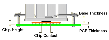
The clip load on the heat source can be calculated by the following tool. Please note that this data is just for reference. Unknown dimensions and tolerances can significantly affect the load on the heat source.
1st, Calculate X value of graph, using the formula below the graph.
2nd, Y value (Clip load) can be found from the intersection of "X value" and "CQZ & QSZ clips performance
line".
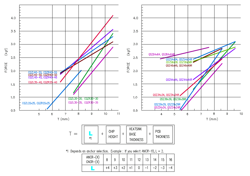
- Clip Load Calculator
| Clip Type | |||
|---|---|---|---|
| Clip |
Force
**.**
kgf
Pressure
**.**
kgf/cm2
|
||
| Anchor Pin | |||
| Heat Sink Base Thickness | mm | ||
| Chip Contact Area | mm x mm |
Input Unit: |
|
| Chip Height | mm | ||
| PCB thickness | mm | ||
A custom clip can be created if none of our standard clips are compatible with your PCB layout.
Please use our online QSZ Clip Design Tool. Simply enter your design information and submit the request.
- Cost & Lead time Information :
- No NRE/Tooling fee is required.
- Estimated unit cost is $20.00 for 10pcs, $3.00 for 100pcs, and $1.50 for 300pcs.
- Prototype lead time is approximately 2 weeks. Production lead time is 2-4 weeks.
© 2011-2023 Alpha Novatech, Inc.