
Online Catalog
Heat sink selection
Select / Design a Heat Sink
1.
Read
before you start
In order to properly select/design a heat sink,we need to clearly specify the operating conditions and calculate a thermal resistance target for the heat sink.
Please answer the following questions in as much detail as possible.
If you cannot answer a question, leave it blank, and we will fill in a typical value based on our experience.
After answering the questions, please push the "Request" button.We will review your responses and provide feedback ASAP.
Please fill in items 1 through 6, answering the questions as completely as possible.
If you are unsure about a question, leave it blank.
After completing all sections, press the "Request" button above to submit your information.
/
2.
Send
when you are done
Please confirm your inputs and enter your contact information along with any additional
relevant information. Once the request is sent, we will review and contact you by email.
Duct Size (H)
mm
mm
Duct Size (W)
mm
mm
Heat Sink (H)
mm
mm
Ambient
°C
°C
Heat Sink (W):
mm
Heat Sink (L): mm
Heat Sink (L): mm
Max Case Temp:
°C
Wattage: W
Wattage: W
Air Flow:
Air Speed: m/s
Air Speed: m/s
Thermal Resistance:
°C/W
Input Data
Contact Information
* The fields with an asterisk(*) are required.
| Company Name * | Department/Division |
|---|---|
| Country * | Name * |
| Email * | Phone # |
Additional Info
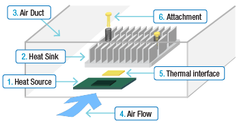
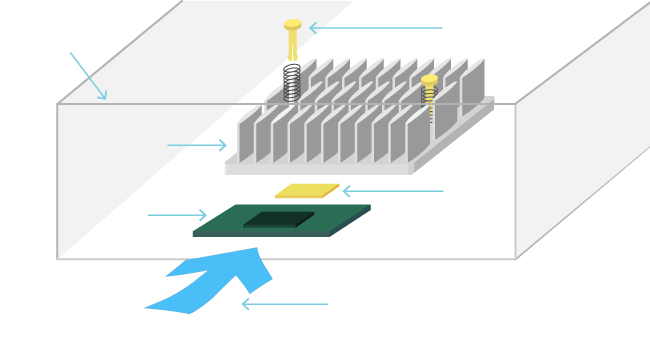
1. Heat Source
2. Heat Sink
3. Air Duct
4. Air Flow
5. Thermal Interface
6. Attachment
1 .
Heat Source
/
2 .
Heat Sink
/
3 .
Air Duct
/
4 .
Air Flow
/
5 .
Thermal Interface
/
6 .
Attachment
/
1.
Heat Source
Input IC Chip (Heat Source) Specification
Target thermal performance
Power consumption(TDP) (W)
Maximum allowed case temperature (°C)
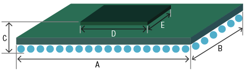
IC chip(heat source) size
| A (mm) | B (mm) | C (mm) | D (mm) | E (mm) |
|---|---|---|---|---|
Chip manufacturer and model number
Additional Info
2.
Heat Sink
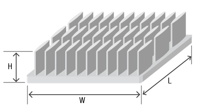
Input Heat Sink Size Requirements
Maximum allowed heat sink size (if any)
| W:Width(mm) | L:Length(mm) | H:Height(mm) |
|---|---|---|
If you only know the height limitation, simply enter this number.
Target thermal resistance (for the heat sink) (°C/W)
Additional Information
Regarding a heat sink size
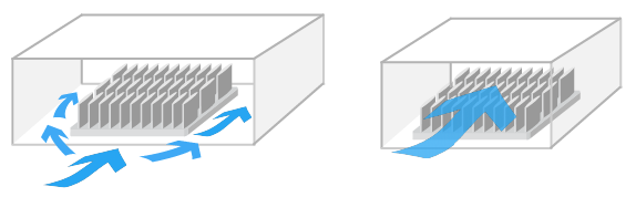
A larger heat sink will typically perform better, as the surface area of the heat sink will become greater. Also, by increasing the volume of the heat sink, the amount of bypass area around the heat sink will be reduced, forcing more airflow to go through the heat sink.
Bypass Air Flow (Large)
Bypass Air Flow (Small)
However, a larger heat sink may require a more complicated and expensive attachment method. Push pins or shoulder screws versus thermal tape or epoxy. (REF:Online Catalog - Heat Sink Attachment)
If mechanical attachment hardware like push pins or shoulder screws are used, holes in the PCB must be located outside of the chip’s footprint. This will require the use of a larger heat sink or a heat sink with attachment tabs.
Close
3.
Air Duct
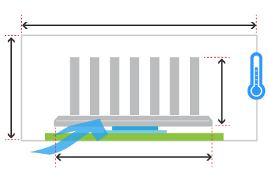
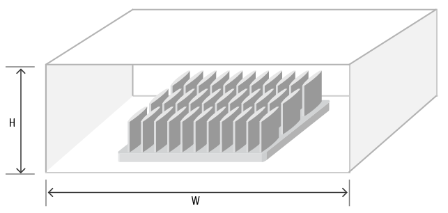
Input Duct Size
Duct Size
Has a formal duct been created to prevent air from bypassing around the heat sink? In the actual environment, if no duct has been created, other components like a daughter card, memory module, PCB components, the chassis, etc..., will act like a duct and help to channel the air. The estimated size of the duct created by these components is useful. If this detailed information is not available, just having height information for the chassis itself can be very useful.
| W:Width(mm) | H:Height(mm) |
|---|---|
Additional Info
4.
Air Flow
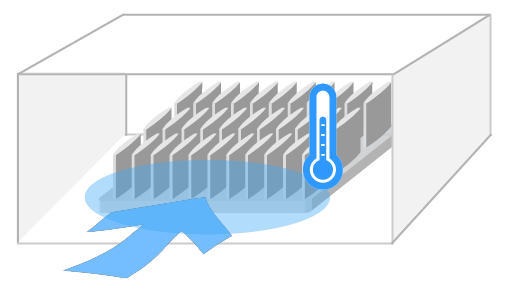
Input Air Flow Conditions
Ambient Temperature (°C)
Target Thermal Performance
Heat sink position
Heat sink position
Air speed
Air speed
(m/s)
Additional Info
Aiflow Condition
The air flow condition can be classified as Natural Convection or Forced convection.
Natural convection is a condition where the air flow is only generated by a a temperature differential and NOT by external means like a fan or blower.
Forced Convection is a condition where air flow IS generated by an external source like a fan or blower.
Greater air speed will result in better thermal performance.
In the actual environment, the air speed generated by a fan or blower will depend on many factors, such as where the components are located relative to the heat sinks, and fin pattern density of the heat sinks that are used.
The air speed used for simulation is ithe inlet air speed, just in front of the heat sink.
5.
Thermal Interface
Input Thermal Interface Material (TIM) Preference
The following is a list of typical Alpha Standard TIM products. We carry many additional TIM products.
If you have requests, please input this information in the memo (Additional Information) section.
Additional Info
Interface Material
Thermal interface material(TIM) fills the small gaps and imperfections between the heat sink and heat source, minimizing the interface thermal resistance.
Please visit Online Catalog - Accessory - Thermal Interface Material.
If you choose adhesive tape for heat sink attachment, the adhesive tape itself is also the thermal interface material.
Pleaes visit Online Catalog - Accessory - Thermally conductive Adhesive Tape.
Generally, as the heat source size becomes smaller, the performance characteristics of the TIM becomes far more significant.
6.
Attachment
Select Attachment Method
Additional Info
Heat Sink Attachment
The heat sink attachment method is one of the most important factors regarding heat sink design. The method of heat sink attachment will have an impact on the selection of thermal interface material. For more details, please visit Online Catalog - Heat Sink Attachment.
Thank you for your request.
If you do not hear from us within 2 business days, please contact our sales department.
Request ID:
Input Data
Contact Information
| Company Name * | Department/Division |
|---|---|
| Country * | Name * |
| Email * | Tel |
| Additional Info | |
Input check
Input check
Input check